This page is part of my exploration re transistor matching.
There are lots of transistor matching circuits out there.
Many ways but the question is which to use. ???
The TTSH build required matched transistors in the filter section.
I matched them via hFE ... not by the usual the Vbe (base-emitter voltage).
I'm hoping I'll get away with it for that instance. However, the TTSH VCA section requires more matched trannies. So it's time I guess to bite the bullet.
Moog has a classic transistor checker schematic (from the mini-moog manual).
Here one current drives another current through the transistors and you need to measure the voltages between the base & emitter.
![]() It calls for a +/- 10V supply and needs a really accurate volt meter.
It calls for a +/- 10V supply and needs a really accurate volt meter.
There is a variation of this circuit on DragonflyAlley.com
It uses a +/-15V supply, a 741 op-amp & 3 resistors.
![]()
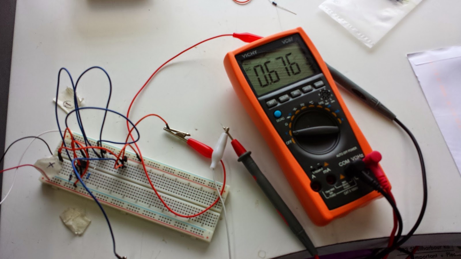
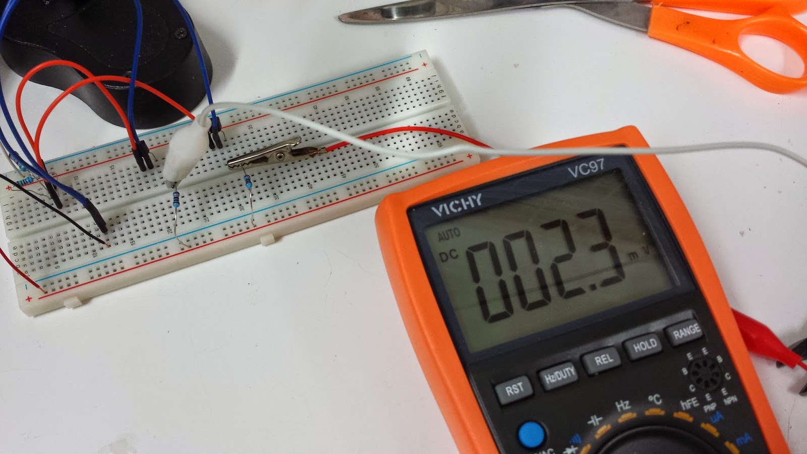
Here are some pics of the breadboarded circuit. (just for the NPN 3904 trannie).
![]()
![]()
![]()
![]() The voltage on the multimeter is the difference between the two transistors. In an ideal world of perfectly matched resistors & transistors the voltage would be zero.
The voltage on the multimeter is the difference between the two transistors. In an ideal world of perfectly matched resistors & transistors the voltage would be zero.
This particular batch of 3906s seem to vary by 0.5 to 4 millivolts.
For completeness here are a few more links to blogs, websites which discuss transistor matching.
Hopefully you will find this useful.
Muffs has a cool thread for DIY Transistor matching if you finally wish to go down this path..
matching transistors - DIY
The famous minimoog tester of Dr. Robert Moog.
MFOS has a great page on how to build transistor matchers.
(MFOS Practical Transistor Matching)
I might try this MFOS matcher later if the earlier attempts aren't successful.
There are lots of transistor matching circuits out there.
Many ways but the question is which to use. ???
The TTSH build required matched transistors in the filter section.
I matched them via hFE ... not by the usual the Vbe (base-emitter voltage).
I'm hoping I'll get away with it for that instance. However, the TTSH VCA section requires more matched trannies. So it's time I guess to bite the bullet.
Moog has a classic transistor checker schematic (from the mini-moog manual).
Here one current drives another current through the transistors and you need to measure the voltages between the base & emitter.

There is a variation of this circuit on DragonflyAlley.com
It uses a +/-15V supply, a 741 op-amp & 3 resistors.
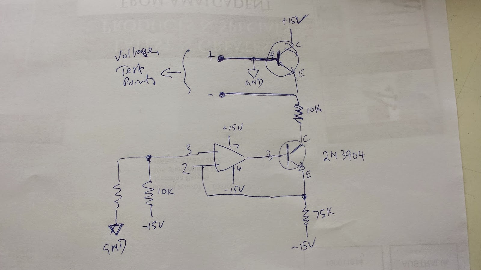
The Op-amp is a 741. (Pin 6 of the 741 connects to the base of the 3904)
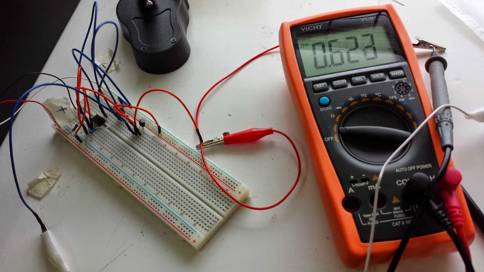
It seems to work though there is lots of voltage fluctuation
Very temp sensitive.
Very temp sensitive.
Ian Fritz also has a transistor matching circuit.
You can download it here.
http://www.dragonflyalley.com/images/TransistorMatching/ianFritz-transmat0011_144.pdf
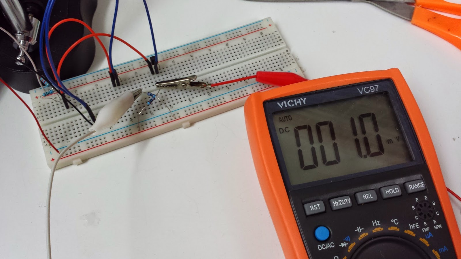
This is a breadboard of the Fritz transistor matcher.
The crossed resistors need to be matched as closely as possible. I guess a variable trim-pot could also be used to get a closer matching between the resistors.
The crossed resistors need to be matched as closely as possible. I guess a variable trim-pot could also be used to get a closer matching between the resistors.
I kinda like it more than the Moog circuit. It's definitely much simpler using just 3 resistors & a diode.
This particular batch of 3906s seem to vary by 0.5 to 4 millivolts.
For completeness here are a few more links to blogs, websites which discuss transistor matching.
Hopefully you will find this useful.
Muffs has a cool thread for DIY Transistor matching if you finally wish to go down this path..
matching transistors - DIY
The famous minimoog tester of Dr. Robert Moog.
MFOS has a great page on how to build transistor matchers.
(MFOS Practical Transistor Matching)
I might try this MFOS matcher later if the earlier attempts aren't successful.