The filter build of the TTSH synthesizer. This is part 7 of my TTSH (Two thousand six hundred) build which is an ARP 2600 clone synth.
You can see my full build thread
HEREI understand this filter is based around the coveted Model 4012 filter, a four-pole low-pass VCF.
The 4012 filter used a design that closely resembled Moog's ladder-filter. This led to a legal dispute between Moog and ARP which forced ARP to design a new filter for their later models.
All the early ARP 2600 (pre 1977) used this filter. It's one of the reasons why the early Blue Marvins, Grey Meanies, the (pre 1977) 2600s & 2601 v1.0 sounded so good.
This is the filter sub-module.
The original design uses 8 pairs of matched and thermally coupled TZ-81 and TZ-581 transistor pairs.There is a Dual FET AD3958,
a LM301 Op Amp & temperature compensation via a 1K87 tempco resistor.The TTSH combines the filter sub-module with the additional main board filter circuitry. To the left (from top to bottom) are marked Ring MOD, VCO1, VCO2, VCO3, Noise, KYBD CV, ADSR, VCO2 (Audio & CV summing).
Post 1976, ARP used the model 4072 filter (which was in turn replaced with the
ARP 4075 4-pole 24dB low pass filter in the ARP Odyssey Mark 3, Omni and Quadra).Some pics of the almost virgin PCB first:
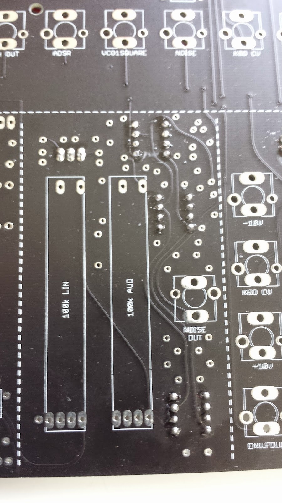
This is the back of the PCB
And the front section
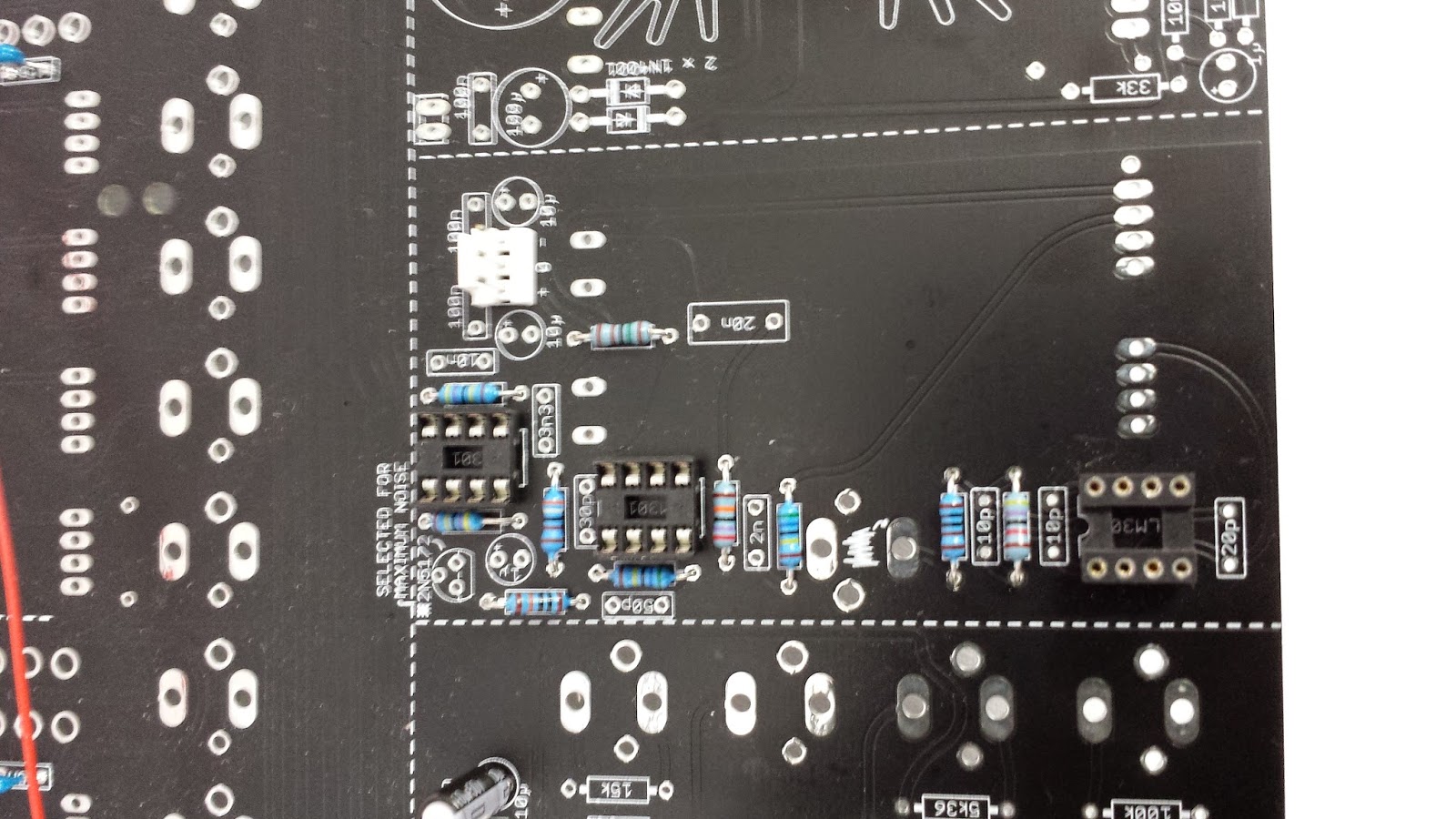
Resistors & diodes first as usual.
These are Multilayer Ceramic Capacitors MLCC - Leaded 47pF 50V.
I hope the slight discrepancy won't cause problems.
Caps & headers in.
The original 4012 filter used 8 pairs of matched and thermally coupled TZ-81 and TZ-581 transistor pairs.
The TZ81 was a NPN made by Sprague.The TZ-581 is a PNP trannie
The TZ-81 is now defunct. The TTSH uses the 2N3904. (its modern equivalent).
The TZ-581 is also defunct. The 2N3906 is a modern equivalent.
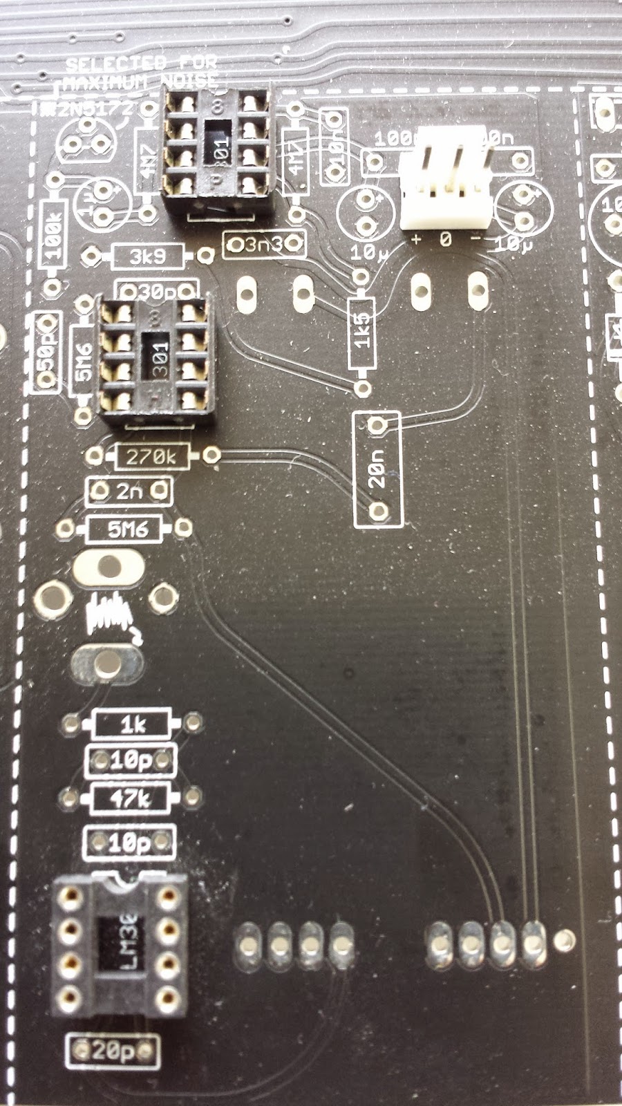
This is what the PCB looks like before the transistors:
Some of the trannies need to be matched.
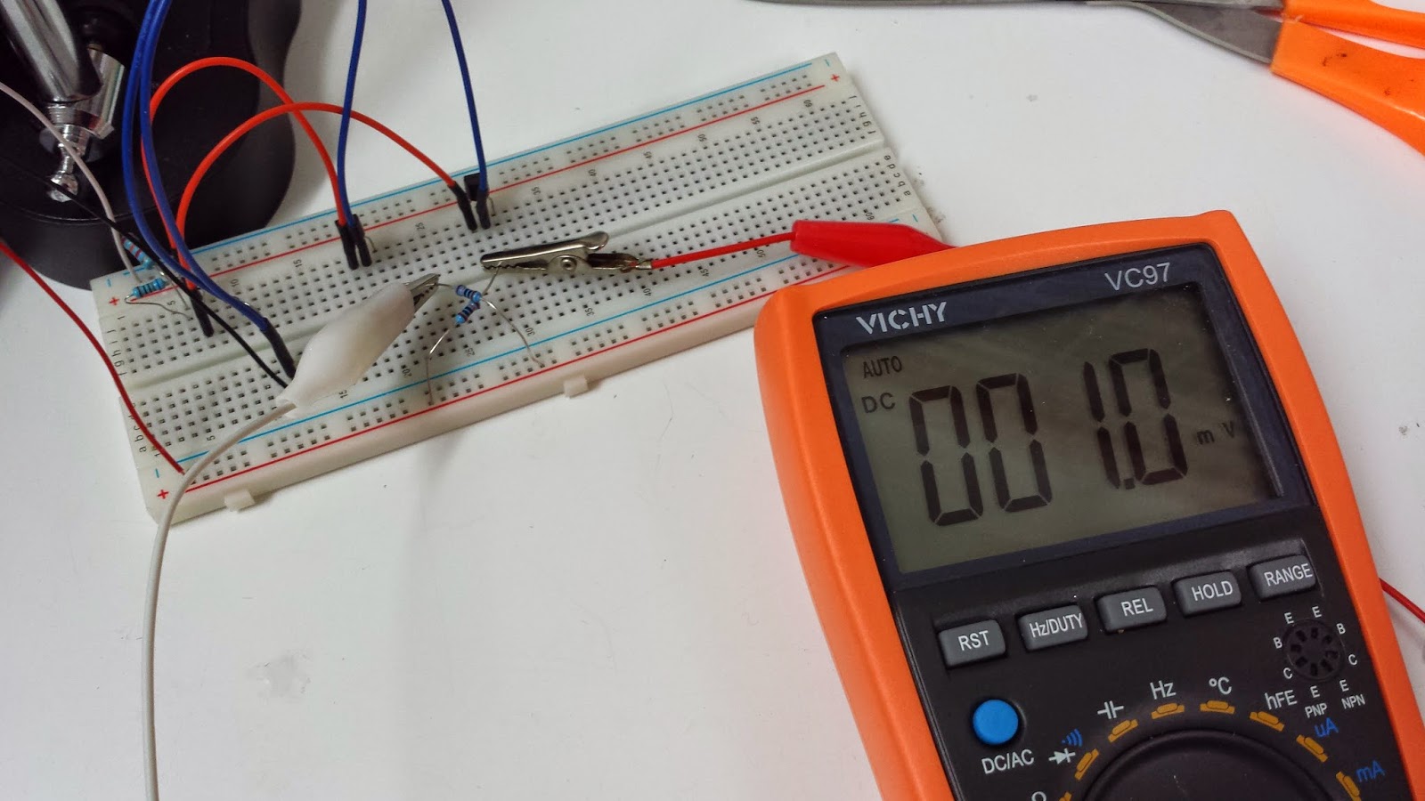
First insert the unmatched transistors:
This is a 2N395. It's a dual JFET
2N395 pinout
Unmatched transistors.
There are lot's of ways to match transistors.
Vbe (base-emitter voltage) Vs Hfe (current gain). ????
And the question of whether its really needed in this case is debatable.
Modern manufacturing tolerances are far tighter than back in the 70s.
I'm buying all my transistors in a single order so they should come from a single manufacturing batch. I guess that matching will only make a difference when your trannies come from several sources.
I'm testing each PCB as I go along & … I'll swap for matched pairs at a later date if I need to.
So far I've not run into any problems, but I found that thermal coupling (thermal compound between the transistors) seems to help.
Anyway, Muffs has a cool thread for DIY Transistor matching if you finally wish to go down this path..
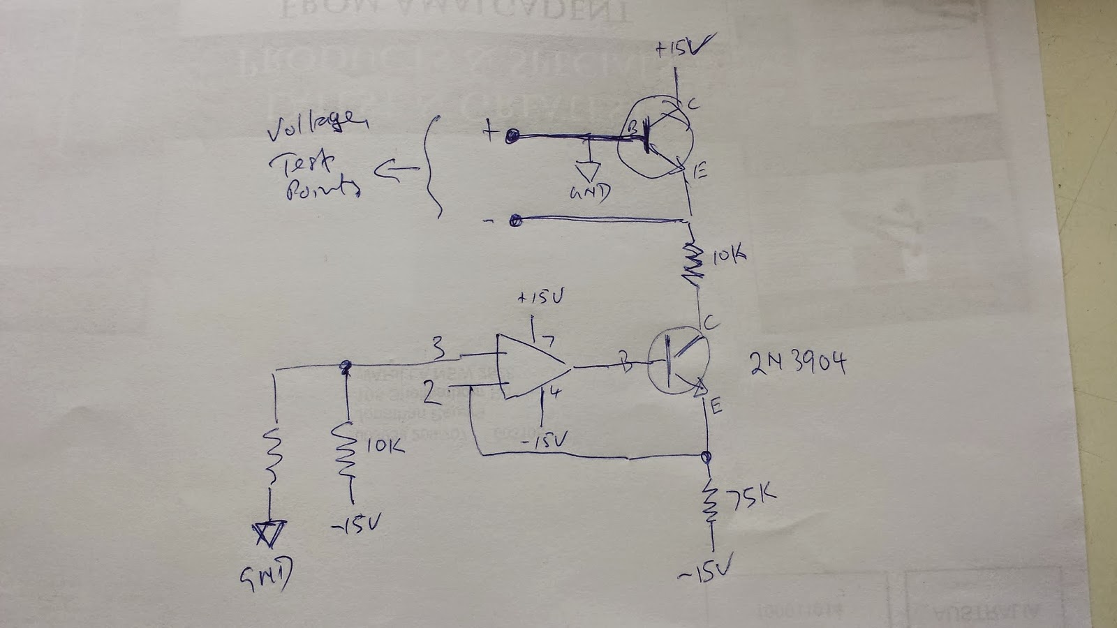
matching transistors - DIY Vbe (base-emitter voltage) matching is the most common type of matching.Eg: the famous tester of
Dr. Robert Moog.Moog assumed you have a +/-10V supply. He measured the base to emitter voltage.
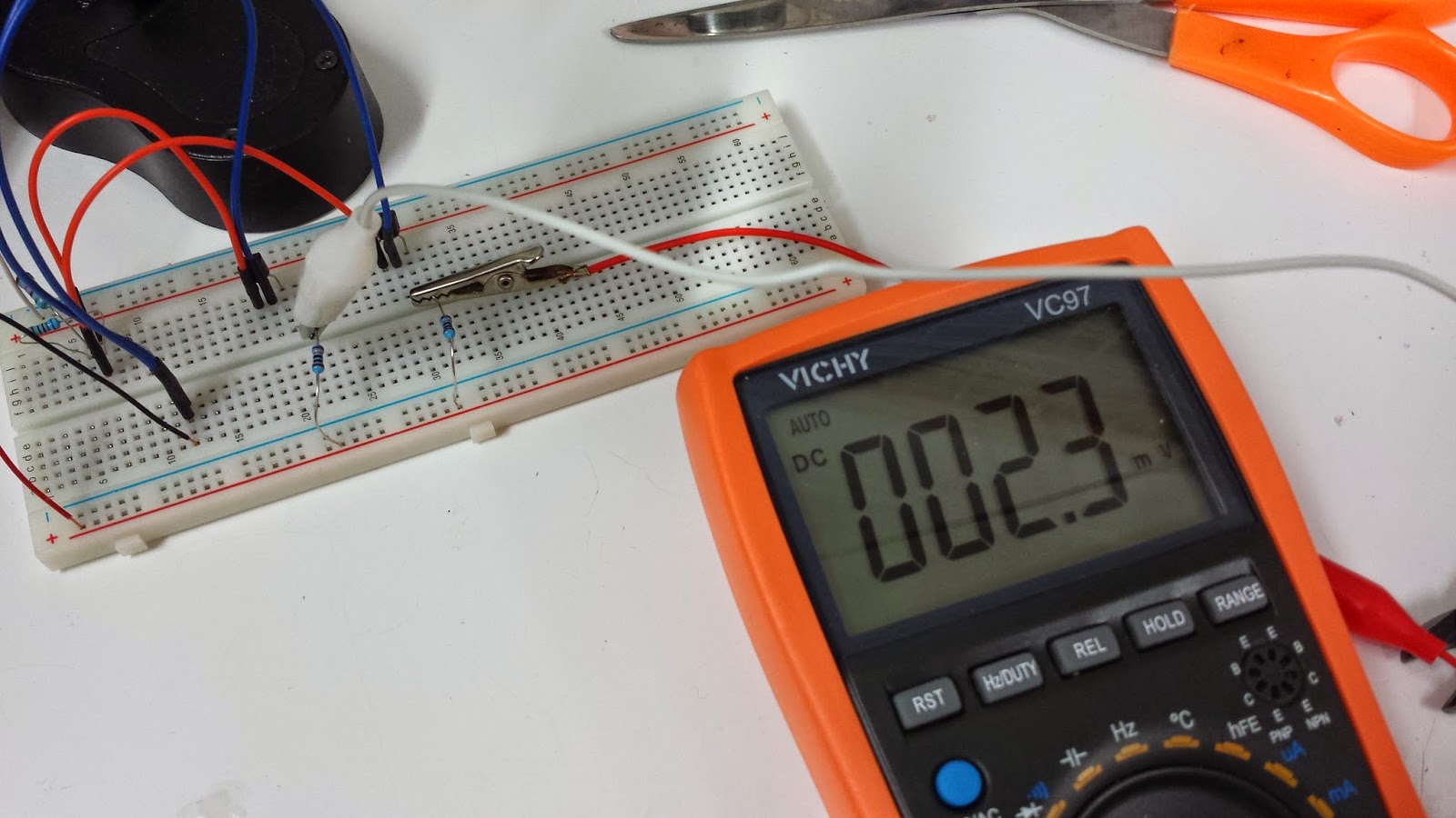
You need a volt meter capable of reading to 0.001Volts DC.
(Sadly my VC97 meter only does 2 decimal points. ... time for a new one I think)
MFOS has a great page on how to build transistor matchers.
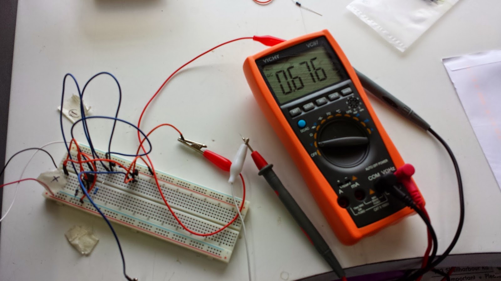
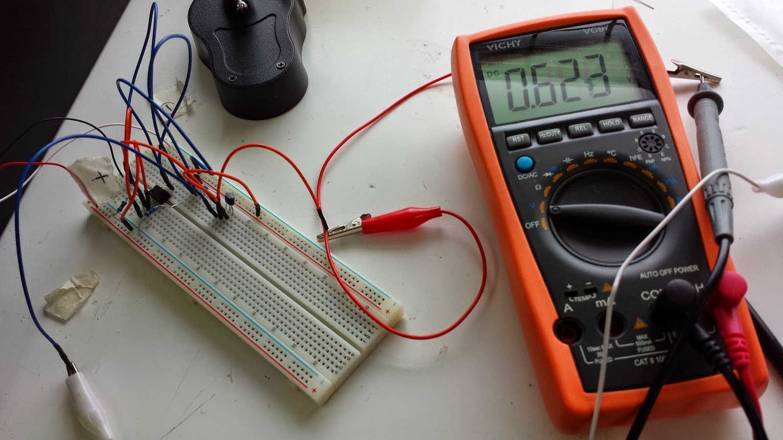
(MFOS Practical Transistor Matching)At the moment I'm using a cheap digital multimeter. (Vichy VC97) with a a h
FE mode.
(It's
useless for Vbe matching).
Matching hFE is really easy to do. First define whether your trannie is NPN or PNP,
then insert the emitter, base & collector into the appropriate hole.The DMM calculates the hFE for IB (In fractions of a mA I think). The value will be displayed on the LCD.
IB = base current
IC = collector current
hFE = DC current gain = IC / IB
The h
FE varies with the current draw, the temperature & the applied voltage ... so I guess if we want to be really precise we should measure this all under the circumstances the transistor will see in its working environment.
![]()
These are my 3904s sorted in order of hFE
Same with the 2N3906s
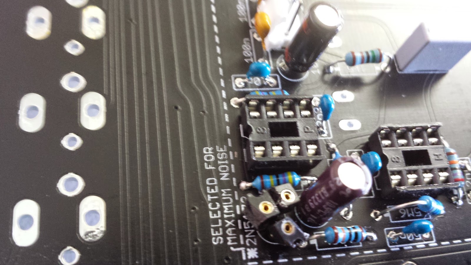
Tempco 1k87 resistor.
The transistor ladder of hFE matched 2N3904s
Trimpots finally.


 These are my 3904s sorted in order of hFE


 .
.