Some notes on using the DX 7.
I only just bought a Mark 1 about a week ago so there is a steep learning curve ahead.
These will be added to over time and hopefully help me to master FM synthesis.
FM synthesis was first developed by John Chowning in 1967 at Stanford Uni, then licensed to yamaha in 1973.it's very different to Subtractive synthesis. There are no VCOs, VCFs or VCAs..
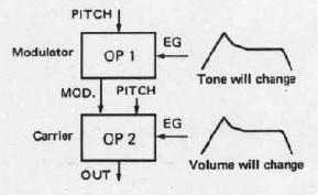
Instead of the VCO, FM uses an operator.
This generates a sine wave.
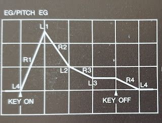
Each operator has the following properties which can be changed :
Pitch (frequency ratio), envelope, scaling, output level, and velocity sensitivity.
In 1983, Yamaha released the DX7 Mk1.
The DX 7 has 6 sine wave operators (an oscillator with a envelope Generator).
They are arranged into either carrier or modulator.
By rearranging the operators, we can generate harmonically rich tones.
These arrangements are known as ALGORITHMs
Carrier - controls the output. It acts like a VCA
Modulator - controls the harmonic content of a sound. It acts like a VCF.
Modulator -----> Carrier -----> output.
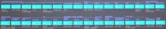
The front panel of the DX 7 Mk 1
It shows things like Algorithms, EGs, Keyboard levels, scaling, the buttons, sliders & LCD panel
Algorithims determine how the 6 operators interact with each other.
There are 32 algorthims.
Picking the correct algorithm is the key to creating a patch.
The algorthims are divided into subgroubs that have similar structures.
(Stacking, Branching, Rooting and Carrier-only)
These groups, will help you to understand how they interact and their sounds
Group 1 - algorthms 1, 2,3, 4, 5, 6.These are stacked algorithms.
2 to 4 operators.
2 towers to 3 towers.
Between these towers there is no frequency modulation. Instead they are added ... ie they are an example of Additive Synthesis.
These types pf algorthims are used for such things as
Strings ( A4 STRINGS ALG 2),
Piano ( A11E.PIANO 1 ALG 5).
Tubular Bells ( A26 TUB BELLS ALG 5).
Algorithm 2 consists of 2 independent towers with operators stacked on top of one another.
gREAT for sounds with high harmonics like strings .
Notice also the feedback loop. You can control the amt of feedback by its Level & Output Level.
We use feedback operators to generate higher harmonically rich tones such as sawtooth waves.
We can also adjust the Frequency Ratio of each operator to generate particular harmonics.
If Operator 2 = 1.00
Operator 1 = 1.00
we will generate a sawtooth sound
If we change the ratio like so:
Operator 2 = 2.00
Operator 1 = 1.00
we will generate a square wave
If we change the ratio like so:
Operator 2 =3.50
Operator 1 = 1.00
we will generate a Bell Tone (in-harmonic tone)
-------------------------------------------
Algorithm 5 is a bit more complex.
We have 3 independent towers with two operator stacking. This is great for bell & electric piano sounds.
In a DX7 with 6 operators, all can be detuned. So you can get amazing chorus like effects.
Like the "Epic pad" sound.
--------------------------------------------------------------------------------------------------------
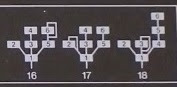
Group 2 - Algorthms 7 to 18.These are a mix of Tower & Branch (like a tree).
Of special note, Algorithms 16, 17 & 18 are pure frequency modulation. (there is no additive component). All FMs converge into operator 1.
Use group 2 algorithms for things like Strings, Brass, Guitar, & Bass patches.
Examples: DX7 Voice ROM 1
A6 Strings (ALG 15)
A4 BRASS 3 (ALG 18)
A12 Guitar ( ALG 8)
A15 Bass 1 (ALG 16).
---------------------------------------------------------------------
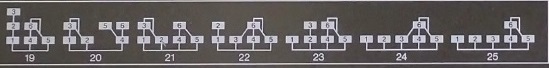
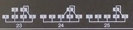
Group 3 - Algorithms 19 to 25These are rooting algos with or without a tower
There are at least 3 carriers in each of these algorithms.
Of particular note, Algos 23, 24 & 25 have one to 3 operators without any modulators.
These are pure sine wave carrier operators.
Group 3 algorithms are used for things like brass, Vibe & pipes.
For example see Voice ROM 1
A1 BRASS 1 (ALG 22),
A21 VIBE 1 (ALG 23)
A18 Pipes (ALG 19)
-----------------------------------------------------------------------------------------------
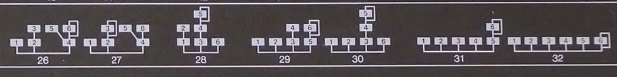
Group 4 - Algorithms 26 to 32These are tower/ branch combinations..
They all have at least 1 pure sine wave carrier only operator.
These are good for organ & bell sounds
Eg : from Voice ROM 1
A17 E.ORGAN 1 (ALG 32)
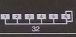
The Algorithm 32 is the simpliest algorithm.
Each operator is independent. Each generates a sine wave.
There is no Frequency modulation. Thus this is an example of pure additive synthesis.


 -----------------------------------------------------------------------------------------------------