There are 3 main modes of operation on the DX7
1. Edit (purple-blue)
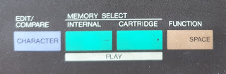
2. Play (white)
3. Function (brown)
![]()
Everything is colour coded
Play Mode (white) is the simpliest and a good place to start.
Here you can access the sounds contained in the internal & external memory.
![]()
The green buttons above PLAY let you select between internal and external sounds.
Just press either green button to activate the 32 (white) switches. Then press the switch to select the preset.
![]()
External sounds can be either ROM or RAM.
![]()
ROM or Read only memory cartridges are non erasable.
You cannot write data to a ROM cartridge.
Each ROM cartridge contains 64 sounds or presets organised into 2 sides... sides A & B. (32 on each side).
Selecting the side (A or B) is accomplished with the select switch on the cartridge itself.
RAM =Random Access Memory .... this is very flexible ... you can both read and write data to it.
This contains 32 voices
It covers various effects you can apply while playing (like aftertouch & Modulation wheel) as well as things like voice data load/save operations and checking the battery.
Functions parameters cannot be saved to memory after the DX is turned off.
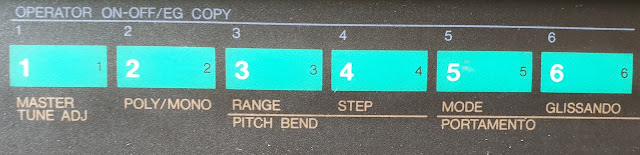
1. Master Tune
2. Poly/Mono
3/4. Pitch Bend (range & Step)
5/6/7 Portamento (mode, Glissando, time)
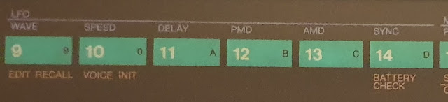
9. Edit recall
10. Voice Initialize
11. Cartridge formatting
14 Battery Check
15/16 Cartridge (save & Load)
17/18/19/20 Modulation Wheel - range, pitch, amplitude, EG Bias
21/22/23/24 Foot Control - range, pitch, amplitude, EG Bias
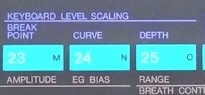
25/26/27/28 Breath Control - range, pitch, amplitude, EG Bias
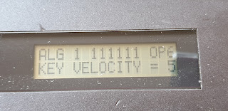
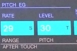
29/30/31/32 After touch - range, pitch, amplitude, EG Bias
-----------------------
![]()
1. Master Tune
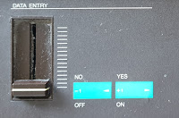
Adjusts the overall tuning ... 150% range. Use the data entry slider to adjust.
2. Poly/Mono
Controls mono vs poly voice
Use Data Entry -1 for poly , and +1 for mono
![]()
3/4. Pitch Bend (range & Step)
Range: between 0 to 12.
0 = no pitch bend. 12 = 2 oct range
Step : Between 0 to 12
0 = smooth pitchbend with no steps.
1 = semitone steps
12 = 1 octave steps.
5/6/7 Portamento (mode, Glissando, time)
Portamento effect depends on mono vs poly mode
eg: on mono use Data Entry -1 for fingered porta , and +1 for full time porta
(see manual)
Glissando - adjusts speed of portamento
----------------------------------------
![]()
9. Edit recall
Allows you to recall a voice that was previously being edited or created.
Use the DATA ENTRY "yes key"
![]()
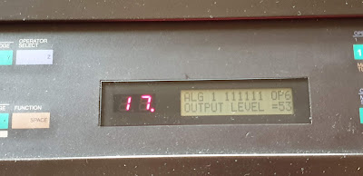
10. Voice Initialize
This sets up a basic voice for you to edit and create new voices.
Press the DATA ENTRY "yes key "
11. Cartridge formatting.
Interestingly this is not written on the DX7 itself.
This formats your RAM cartridge
Press the DATA ENTRY "yes key "
14 Battery Check
Battery voltage should be between 2.2 to 3V.
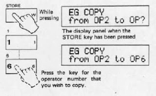
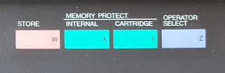
15/16 Cartridge (save & Load)
Save= this saves the 32 internal memeory voices to a cartridge.
Load= This loads all 32 voices from a cartridge into internal memory.
--------------------------------------------------------------
![]()
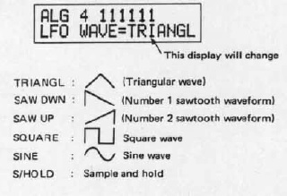
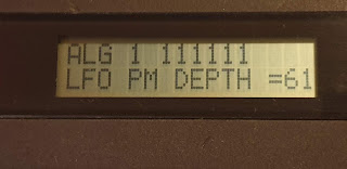
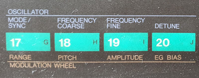
17/18/19/20 Modulation Wheel
Used to control the amount of LFO modulation to range, pitch, amplitude, EG Bias
Range : 0 to 99
Pitch : on or off
Amplitude : on or off
----------------------------------
![]() 21/22/23/24 Foot Control - range, pitch, amplitude, EG Bias
21/22/23/24 Foot Control - range, pitch, amplitude, EG Bias
---------------------------------------
![]()
25/26/27/28 Breath Control - range, pitch, amplitude, EG Bias
29/30/31/32 After touch - range, pitch, amplitude, EG Bias
----------------------------
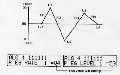
FM Index
---------------------------
1. Edit (purple-blue)
2. Play (white)
3. Function (brown)

Everything is colour coded
Play Mode
Play Mode (white) is the simpliest and a good place to start.
Here you can access the sounds contained in the internal & external memory.

The green buttons above PLAY let you select between internal and external sounds.
Just press either green button to activate the 32 (white) switches. Then press the switch to select the preset.

External sounds can be either ROM or RAM.

ROM or Read only memory cartridges are non erasable.
You cannot write data to a ROM cartridge.
Each ROM cartridge contains 64 sounds or presets organised into 2 sides... sides A & B. (32 on each side).
Selecting the side (A or B) is accomplished with the select switch on the cartridge itself.
RAM =Random Access Memory .... this is very flexible ... you can both read and write data to it.
This contains 32 voices
Function Mode
Press the brown function key to enter this mode.It covers various effects you can apply while playing (like aftertouch & Modulation wheel) as well as things like voice data load/save operations and checking the battery.
Functions parameters cannot be saved to memory after the DX is turned off.
1. Master Tune
2. Poly/Mono
3/4. Pitch Bend (range & Step)
5/6/7 Portamento (mode, Glissando, time)
9. Edit recall
10. Voice Initialize
11. Cartridge formatting
14 Battery Check
15/16 Cartridge (save & Load)
17/18/19/20 Modulation Wheel - range, pitch, amplitude, EG Bias
21/22/23/24 Foot Control - range, pitch, amplitude, EG Bias
25/26/27/28 Breath Control - range, pitch, amplitude, EG Bias
29/30/31/32 After touch - range, pitch, amplitude, EG Bias
-----------------------

1. Master Tune
Adjusts the overall tuning ... 150% range. Use the data entry slider to adjust.
2. Poly/Mono
Controls mono vs poly voice
Use Data Entry -1 for poly , and +1 for mono

3/4. Pitch Bend (range & Step)
Range: between 0 to 12.
0 = no pitch bend. 12 = 2 oct range
Step : Between 0 to 12
0 = smooth pitchbend with no steps.
1 = semitone steps
12 = 1 octave steps.
5/6/7 Portamento (mode, Glissando, time)
Portamento effect depends on mono vs poly mode
eg: on mono use Data Entry -1 for fingered porta , and +1 for full time porta
(see manual)
Glissando - adjusts speed of portamento
----------------------------------------

9. Edit recall
Allows you to recall a voice that was previously being edited or created.
Use the DATA ENTRY "yes key"

10. Voice Initialize
This sets up a basic voice for you to edit and create new voices.
Press the DATA ENTRY "yes key "
11. Cartridge formatting.
Interestingly this is not written on the DX7 itself.
This formats your RAM cartridge
Press the DATA ENTRY "yes key "
14 Battery Check
Battery voltage should be between 2.2 to 3V.
15/16 Cartridge (save & Load)
Save= this saves the 32 internal memeory voices to a cartridge.
Load= This loads all 32 voices from a cartridge into internal memory.
--------------------------------------------------------------

17/18/19/20 Modulation Wheel
Used to control the amount of LFO modulation to range, pitch, amplitude, EG Bias
Range : 0 to 99
Pitch : on or off
Amplitude : on or off
----------------------------------

---------------------------------------

25/26/27/28 Breath Control - range, pitch, amplitude, EG Bias
29/30/31/32 After touch - range, pitch, amplitude, EG Bias
----------------------------
FM Index
---------------------------


 ...
...


 ...
...


